Welcome to Shenzhen Dongshengyuan Electrical Equipment Co., Ltd.

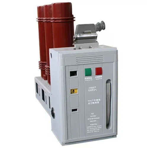
Vacuum Casting of Epoxy Insulators for MV Switchgear: Process, Defects, and What Buyers Should Verify
This article analyzes partial discharge risks of vacuum cast epoxy insulators for medium voltage switchgear. It explains void and interfacial defects, key vacuum casting processes, quality verification and procurement technical points, and differentiates vacuum casting from APG pressure gelation.
Nov 11,2026
Most partial discharge in medium-voltage switchgear does not start in the gas. It starts inside a piece of cast epoxy that looked perfect when it left the mould.
Short answer
Vacuum casting is the process of filling a mould with epoxy resin, hardener and silica filler under reduced pressure so that air is removed before and during the pour. The vacuum is what prevents voids. Voids are what cause partial discharge. Partial discharge is what destroys the insulator, usually years later. A casting process is therefore judged not by how the part looks, but by void content, filler distribution, cure degree, and the condition of the bond between the epoxy and any metal insert.
Quick facts
Parameter | Typical value | Why it matters | Where it comes from |
Silica filler content | 60-70% by weight | Lowers thermal expansion, raises thermal conductivity, reduces shrinkage | Formulation data sheet |
Resin mix temperature | 40-60 C | Viscosity must be low enough to wet the filler and fill the mould | Process specification |
Degassing pressure | Not more than 100 Pa | Removes dissolved and entrained air before the pour | Process specification |
Casting pressure | 300-500 Pa | Keeps air out while the mould fills | Process specification |
Gel time at 140 C | 10-30 min | Too fast and the part gels before it fills; too slow and filler settles | Formulation data sheet |
Cure and post-cure | 120-140 C, 4-8 h; post-cure 130-140 C, 10-20 h | Determines glass transition temperature and residual stress | Process specification |
Glass transition (Tg) | 105 C minimum, typically 110-120 C | Above Tg the mechanical and dielectric properties fall steeply | DSC measurement |
Coefficient of thermal expansion | 25-35 ppm/K | Mismatch against the copper insert drives interface stress | TMA measurement |
Cure shrinkage | 0.5-1.5% linear | Sets the residual stress locked in at cool-down | Formulation data sheet |
Partial discharge limit | Not more than 10 pC at 1.2 x Um | The acceptance criterion that actually correlates with life | IEC 62271-1 / GB/T 11022 |
Critical void size | About 0.5 mm in a high-stress region | A void this size can initiate discharge at operating voltage | Design and test practice |
What is vacuum casting, and why does it decide the life of the insulator instead of the shape?
A cast epoxy insulator performs three functions at once: it holds the conductor in place, it provides the creepage path along its surface, and it provides the dielectric strength through its bulk. The first is a mechanical problem, the second is a geometry problem, and the third is a materials problem. Vacuum casting is the only one of the three that is invisible after the fact.
The reason voids matter so much is field concentration. The dielectric strength of air at atmospheric pressure is roughly 3 kV per millimetre, against 20 to 30 kV per millimetre for filled epoxy. A void inside the casting is therefore a small pocket of a much weaker dielectric sitting inside a much stronger one. Under an alternating field, the stress in the void is higher than in the surrounding resin, because the field distributes according to permittivity and the void has the lower permittivity. Once the field in the void exceeds the inception value, it breaks down, and the resulting discharge erodes the void wall.
Erosion is slow and cumulative. This is why a void does not fail a routine test at the factory. It fails after two, five, or twelve years of service, and when it does, the failure is a flashover with no external cause that anyone can find.
What are the process steps, in order?
- Formulation and pre-treatment. The silica filler is dried, because surface moisture on the filler is one of the main sources of gas during cure. The resin and hardener are held at separate controlled temperatures, typically 40-60 C for the resin and 80-100 C for the anhydride hardener, so that the two reach a workable viscosity when mixed.
- Mixing and dispersion. The filler is dispersed into the resin under vacuum or in a planetary mixer. The target is not just uniform concentration but the elimination of agglomerates, because a cluster of filler particles is a stress raiser as well as a flow obstruction.
- Degassing. The mixture is held under vacuum, typically below 100 Pa, for 30 to 60 minutes with slow agitation. This is the step that removes entrained air. It is also the step most often shortened under production pressure, and the resulting parts still look acceptable.
- Mould preparation and insert placement. The mould is cleaned, release agent applied, and the metal insert positioned. The insert is usually preheated, because a cold insert chills the resin at the interface, raises local viscosity, and produces a weak bond line.
- Casting. The mould is evacuated to 300-500 Pa and the mixture is poured. The pressure is slightly higher than the degassing pressure but still far below atmosphere, so the filling front does not entrain air. The pour rate is matched to the gel time: too slow and the mixture gels in the runner, too fast and it can trap air at a sharp corner.
- Cure. Gelation at 120-140 C for the period specified by the formulation, typically 4 to 8 hours for a thick part. During this stage the resin crosslinks and shrinks, and the shrinkage is constrained by the insert.
- Post-cure. A further hold at 130-140 C for 10 to 20 hours. This is not optional. Post-cure completes the conversion of the epoxy network and raises the glass transition temperature. A part that is demoulded and shipped without adequate post-cure will have a Tg close to its service temperature, and its mechanical properties will drift in service.
- Controlled cool-down. The part is cooled slowly, and this is where residual stress is set. Cooling from 140 C to 20 C is a 120 K excursion. With a coefficient of thermal expansion around 30 ppm/K, the epoxy wants to contract about 0.36 percent while the copper insert contracts only about 0.20 percent. The difference has to be absorbed at the interface, and if it is absorbed as locked-in stress rather than as elastic strain, the part carries a built-in crack initiation site from day one.
Which process parameters actually matter?
Four of them, in this order: vacuum quality at degassing, filler content, cure and post-cure profile, and insert preparation.
Vacuum quality is first because it is the only parameter that directly controls void content, and void content is the only defect that is invisible from outside. A degassing pressure that sits at 500 Pa instead of 100 Pa still produces a part that passes a visual inspection and a dimensional check.
Filler content is second because it controls almost everything else. Raising the silica content from 60 to 68 percent lowers the coefficient of thermal expansion, raises thermal conductivity, reduces cure shrinkage, and raises the elastic modulus. All of those are good for interface stress. But it also raises the viscosity, which makes filling harder and makes void entrapment more likely. This is the central trade-off of the formulation, and it is why two suppliers can both claim 65 percent filler and deliver very different parts.
Cure profile is third because under-cure is invisible. A part with a Tg of 95 C looks identical to one with a Tg of 115 C. It only reveals itself when the switchgear carries load in summer and the insulator softens, losing modulus exactly when the mechanical stress from the conductor is highest.
Insert preparation is fourth but not least. The bond between epoxy and metal is a mechanical and chemical joint. A release agent that migrates onto the insert, an oxidised copper surface, or a missing coupling agent all produce a bond line that is sound at 20 C and separates at 100 C.
Which defects matter, and how do they show up?
Defect | How it forms | How it shows up | Severity |
Bulk voids | Incomplete degassing, air entrained during pour | Partial discharge above 10 pC, often only when warm | High |
Interface delamination | Weak insert bond, thermal stress at cool-down | PD at the insert, sometimes a visible gap after sectioning | High |
Thermal cracks | Fast cool-down, high residual stress, sharp geometry | Crack runs from the insert to the surface, visible or dye-penetrant | High |
Filler settling | Long gel time, low viscosity, tall part | Density gradient top to bottom, lower CTE at the base | Medium |
Incomplete cure | Short post-cure, low oven temperature | Low Tg on DSC, softening under load | Medium |
Surface porosity | Mould contamination, moisture on the release film | Cosmetic, but can seed surface tracking in polluted conditions | Low to medium |
The severity ranking has one important asymmetry. Bulk voids and interface delamination are both internal, but delamination is worse, because a gap at the metal-epoxy interface concentrates stress at the same place where the field is highest. A void in the middle of the resin body is surrounded by good material; a void at the insert is at the triple point where conductor, insulation and air all meet.
How is the result verified?
There is no single test that proves a casting is good. Verification is a stack of four measurements, and they answer different questions.
- Partial discharge test at 1.2 times the rated voltage, with the acceptance limit at 10 pC. This is the only test that directly probes what actually kills the insulator. It is also the test most sensitive to test technique: a dirty surface, an ungrounded nearby object, or a loose connection will produce readings that have nothing to do with the casting.
- Glass transition temperature by DSC. A single sample per batch is enough to catch an oven that drifted or a post-cure that was skipped.
- Filler content by thermogravimetric analysis or ashing. Confirms that the formulation in the tank matches the formulation on the drawing.
- Radiography or computed tomography for critical parts. X-ray will show large voids and insert misalignment. Ultrasound is of limited use in filled epoxy because the filler scatters the beam, which is a point often glossed over in equipment brochures.
A fifth check, less common but very informative, is the water immersion followed by PD test. It simulates years of humidity in a week. A part with a marginal interface bond will show a PD rise after immersion that a good part will not.
What should a buyer ask for?
- The degassing pressure and holding time, in writing, not as a general statement about vacuum casting but as a number on the process card.
- The filler content by weight, with the measurement method, and the batch-level TGA records.
- The cure and post-cure temperature profile with tolerances, and the Tg value with the measurement method.
- The PD test report showing the test voltage, the background noise level, and the actual measured values rather than a pass or fail.
- The insert preparation method, including surface treatment and coupling agent, and whether the insert is preheated.
- A sectioned sample or a CT scan for the first article, because a section through the insert is the fastest way to see a delamination that no electrical test will reveal at room temperature.
Frequently asked questions
Is vacuum casting the same as pressure gelation?
No. Vacuum casting fills the mould under vacuum and cures in the same mould at moderate pressure. Pressure gelation, usually called APG, injects the mixture into a closed mould that is already at cure temperature and holds it under positive pressure during gelation. APG gives shorter cycles and better dimensional consistency for high-volume small parts. Vacuum casting gives lower void content and is preferred for large parts and for parts with heavy inserts. The two processes are often used for different products by the same factory.
Does a higher filler content always mean a better insulator?
No. Higher filler lowers thermal expansion and raises thermal conductivity, which is good. Above about 70 percent by weight the viscosity rises steeply, the mixture becomes difficult to degas, and the risk of void entrapment outweighs the benefit. The optimum is determined by the part geometry, not by a universal number.
Can partial discharge in a casting be repaired?
No. A casting with internal discharge is scrap. Surface tracking can sometimes be dressed and re-tested, but an internal void or a delaminated interface cannot be re-impregnated in a finished part. This is why the process controls matter more than the final test: the test can only reject, it cannot fix.
Why does the PD test sometimes pass cold and fail warm?
Because moisture migrates. Water absorbed in the resin or adsorbed on a void wall redistributes when the part reaches operating temperature, and a small void that was dry enough to stay below inception when cold can exceed it when warm. The same mechanism makes a marginal interface bond worse at temperature, because the epoxy expands more than the metal and the gap opens.
What is the single most common cause of a failed casting?
In our experience it is not the formulation and it is not the mould. It is a shortened degassing cycle. When production is behind schedule, the degassing hold is the step that gets trimmed, because nothing visible changes when it is.
How long should a casting be expected to last?
There is no fixed number, because life is governed by the discharge inception margin rather than by time. A casting with no voids above the critical size, a sound insert bond, and a Tg well above the service temperature will typically outlast the switchgear it sits in. A casting with a 0.5 mm void at the insert may fail in three years. The difference is entirely in the process records, not in the appearance.
PREVIOUS:
Related News

From June 5th to 8th, 2025, Shenzhen Dongshengyuan Electrical Equipment Co., Ltd. (hereinafter referred to as "Dongshengyuan Electric") participated in the Southeast Asia Electricity and Energy Exhibition (SEAPAE) held in Jakarta, Indonesia. During the exhibition, the company highlighted its three core product lines: high-voltage and low-voltage distribution switchgear, intelligent circuit breakers, and environmentally friendly load switches. These products are designed to provide targeted solutions for the high temperature and high humidity environments commonly found in Southeast Asia, as well as the growing demand for new energy access. They have successfully attracted over 200 industry customers for business negotiations.
The difference between circuit breakers and vacuum circuit breakers
Circuit breaker is an abbreviation for pole type circuit breaker. Circuit breakers are also vacuum circuit breakers
1B601, Lefu Square, No. 481 Guangming Avenue, Dongkeng Community, Fenghuang Street, Guangming District, Shenzhen
Request Quote
Note: Please leave your contact information and our professionals will contact you as soon as possible!